MAIN PUBLICATION :
| Home � TECHNOLOGY � Wind Turbine Technology � Technology trends � Rotor and nacelle mass |

|
Rotor and Nacelle Mass
Rotor mass trends are always complicated by quite different material solutions, choice of aerofoils and design tip speed, all of which can impact very directly on the solidity (effectively surface area) and mass of a blade. Table 3.3 shows blade mass of very large wind turbines.
The introduction into Enercon’s E126 design of a jointed blade with a steel spar on the inner blade is a clear example of where blade technology is radically different from most other large blades.
Table 3.3: Blade Mass of Very Large Wind Turbines
Diameter [m] Blade Mass [tonne] Normalised mass[1][tonne] BARD VM 122 26 28 E112 114 20 24 M5000 116 17 20 REpower 5M 126 18 18 Note: The ‘normalised mass’ is an approximate adjustment to bring all the designs to a common point of reference relative to any one design (in this case REpower 5M), taking account of different diameters and different relations between rated power and diameter.
BARD has also made an interesting decision in blade design, eliminating carbon fibre reinforcement from their blades. Their blade design preserves a very large chord on the inboard section. On most blade designs, maximum chord is usually limited to less than the aerodynamic optimum, in order to facilitate manufacturing, handling and transport. BARD will directly ship their blades from a dockside manufacturing site, avoiding the land transport issues with very large blades. LM also avoids carbon reinforcement in their latest LM 61.5 blade.
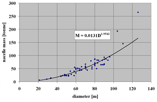
Figure 3.25: Scaling of Wind Turbine Nacelle System Mass
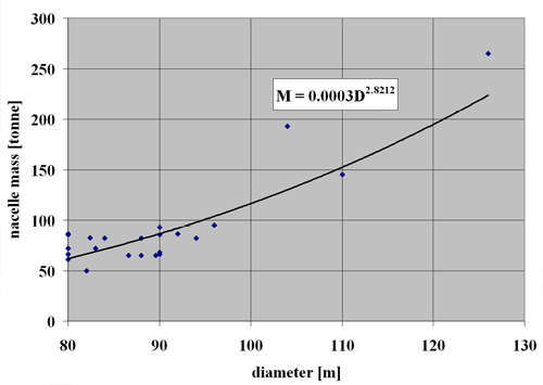
For any given design style, nacelle mass is very much determined by turbine torque rating, which scales as cube of diameter. This implies that, with consistent design at the same level of technology development, the scaling exponent of nacelle mass will be cubic. Considering data from various public sources, it appears (Figure 3.25) that nacelle mass scales approximately as the square of diameter. It is clear, however, that the largest turbines deviate substantially from the trend line and, considering only modern large turbines above 80 m, the exponent is seen to be approximately cubic (Figure 3.26).
Figure 3.26: Scaling of Nacelle System Mass (Turbines > 80 m diameter)
Manufacturers are continually introducing new concepts in drive train layout, structure and components to reduce mass and cost, but avoiding the cubic scaling (or worse when gravity loads begin to dominate) and increases in system mass and cost linked to up-scaling present technology is being explored in depth in the UPWIND project. This project includes an exploration of the technical and economic feasibility of 10 and 20 MW wind turbines.
| << Hub height | Transport and installation >> |
| Acknowledgements | Sitemap | Partners | Disclaimer | Contact | ||
|
coordinated by  |
supported by  |
The sole responsibility for the content of this webpage lies with the authors. It does not necessarily reflect the opinion of the European Communities. The European Commission is not responsible for any use that maybe made of the information contained therein. |


