MAIN PUBLICATION :
| Home � TECHNOLOGY � Offshore � Wind farm design offshore � Electrical system |

|
Electrical System
An offshore wind farm electrical system consists of six key elements:
- Wind turbine generators;
- Offshore inter-turbine cables (electrical collection system);
- Offshore substation (if present);
- Transmission cables to shore;
- Onshore substation (and onshore cables); and
- Connection to the grid.
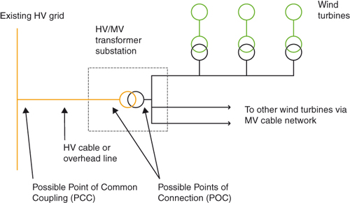
Figure 5.11 illustrates these schematically and the following sub-sections describe them in more detail.
Figure 5.11: Typical Single Line Diagram
The design of the electrical system is determined by the characteristics of the wind turbine generators and of the network to which the project is to be connected, as well as regulations imposed upon it, notably through Grid Codes. The network operator controls the grid to meet its operational objectives and also requires a degree of control over large generators (which may include offshore wind farms). Additionally, the wind farm must be designed to respond appropriately to grid faults. These demands can be expected for any large wind farm located offshore (see Part II).
Wind turbine control and electrical systems are constantly evolving to provide improved characteristics and fault response for the purpose of grid integration. Nevertheless, the wind farm electrical system can be expected to have additional functional requirements in addition to the basic transmission from turbines to the grid connection point.
OFFSHORE SUBSTATIONS
Offshore substations are used to reduce electrical losses by increasing the voltage and then exporting the power to shore. Generally a substation does not need to be installed if:
- The project is small (~100 MW or less);
- It is close to shore (~15 km or less); or
- The connection to the grid is at collection voltage (e.g. under 36 kV).
Most early offshore wind projects met some or all of these criteria, so were built without an offshore substation. However, most future offshore wind farms will be large and/or located far from shore, and so will require one or more offshore substations.
Offshore substations typically serve to step-up the voltage from the site distribution voltage (30 to 36 kV) to a higher voltage (say 100 to 220 kV), which will usually be the connection voltage. This step-up dramatically reduces the number of export circuits (subsea cables) between the offshore substation and the shore. Typically, each export circuit may be rated in the range 150 to 200 MW.
Such substations may be configured with one or more export circuits. Future units will be larger and more complex. To date, no standard substation layout has yet evolved.
For projects located far from the grid connection point, or of several hundred megawatts in capacity, AC transmission becomes costly or impossible, due to cable-generated reactive power using up much of the transmission capacity. In such cases, high voltage DC (HVDC) transmission is becoming an option. Such a system requires an AC/DC converter station both offshore and onshore; both stations are large installations.
ONSHORE SUBSTATIONS
Design of the onshore substation may be driven by the network operator, but there will be some choices to be made by the project developer. Generally, the onshore substation will consist of switchgear, metering, transformers and associated plant. The onshore substation may also have reactive compensation equipment, depending on the network operator requirements and the design of the offshore network.
SUBSEA CABLES
Subsea cables are of well-established design. Each circuit runs in a single cable containing all three phases and optical fibre for communications, with a series of fillers and protective layers and longitudinal water blocking to prevent extensive flooding in the event of the external layers failing.
Inter-turbine (array) cables are typically rated at 30 to 36 kV and installed in single lengths from one turbine to its neighbour, forming a string (collection circuit) feeding the substation. Each collection circuit is usually rated up to 30 MW. Export cables are of similar design but for higher voltage, typically 100 to 220 kV. Cables are terminated at each structure through a vertical tube from seabed to above water level (J-tube or I-tube) and into conventional switchgear.
Long-term reliability of the subsea cables is a major concern, addressed mainly by ensuring the safe burial of the cables at a depth that avoids damage from trawlers and anchors and the exposure of cables to hydrodynamic loading.
| << Future trends for offshore wind | Installation >> |
| Acknowledgements | Sitemap | Partners | Disclaimer | Contact | ||
|
coordinated by  |
supported by  |
The sole responsibility for the content of this webpage lies with the authors. It does not necessarily reflect the opinion of the European Communities. The European Commission is not responsible for any use that maybe made of the information contained therein. |

