MAIN PUBLICATION :
| Home � TECHNOLOGY � Wind farm design � Infrastructure � Electrical works |

|
Electrical Works
The turbines are interconnected by a Medium Voltage (MV) electrical network, in the range 10 to 35 kV. In most cases this network consists of underground cables, but in some locations and some countries overhead lines on wood poles are adopted. This is cheaper but creates greater visual influence. Overhead wood pole lines can also restrict the movement and use of cranes.
The turbine generator voltage is normally classed as ‘low’, in other words below 1,000 V, and is often 690 V. Some larger turbines use a higher generator voltage, around 3 kV, but this is not high enough for economical direct interconnection to other turbines. Therefore, it is necessary for each turbine to have a transformer to step up to Medium Voltage (MV), with associated MV switchgear. This equipment can be located outside the base of each turbine. In some countries these are termed ‘padmount transformers’. Depending on the permitting authorities and local electricity legislation, it may be necessary to enclose the equipment within GRP or concrete enclosures. These can be installed over the transformers, or supplied as prefabricated units complete with transformers and switchgear.
However, many turbines now include a transformer as part of the turbine supply. In these cases the terminal voltage of the turbine will be at MV, in the range 10 to 35 kV, and can connect directly to the MV wind farm network without the need for any external equipment.
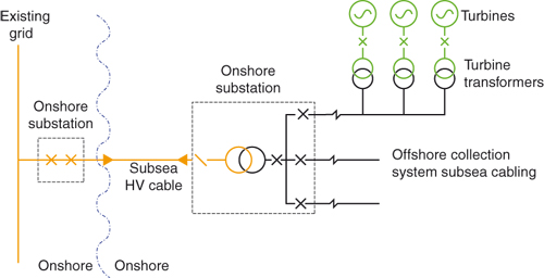
The MV electrical network takes the power to a central point (or several points, for a large wind farm). A typical layout is shown in Figure 4.8. In this case the central point is also a transformer substation, where the voltage is stepped up again to high voltage (HV, typically 100 to 150 kV) for connection to the existing electricity network. For small wind farms (up to approximately 30 MW), connection to the local MV network may be possible, in which case no substation transformers are necessary.
The MV electrical network consists of radial ‘feeders’. Unlike industrial power networks, there is no economic justification for providing ring arrangements. Therefore a fault in a cable or at a turbine transformer will result in all turbines on that feeder being disconnected by switchgear at the substation. If the fault takes considerable time to repair, it may be possible to reconfigure the feeder to allow all turbines between the substation and the fault to be reconnected.
Figure 4.8 shows two possible locations for the Point of Connection (POC). Definitions of the POC vary from country to country (variously called delivery point, point of interconnection or similar), but the definitions are similar: it is the point at which responsibility for ownership and operation of the electrical system passes from the wind farm to the electricity network operator. More complex division of responsibilities is possible (for example, the wind farm developer may build and install equipment, which then is taken over by the network operator), but this is unusual.
The revenue meters for the wind farm will usually be located at or close to the POC. In some cases where the POC is at HV, the meters may be located on the MV system to save costs. In this case it is usual to agree correction factors to account for electrical losses in the HV/MV transformer.
Figure 4.8 also shows a possible location of the Point of Common Coupling (PCC). This is the point at which other customers are (or could be) connected. It is therefore the point at which the effect of the wind farm on the electricity network should be determined. These effects include voltage step changes, voltage flicker, and harmonic currents. Grid issues are discussed in detail in Part II: Grid Integration. Often the PCC coincides with the POC.
Figure 4.8: A Typical Electrical Layout
Source: Garrad Hassan
The design requirements for the wind farm electrical system can be categorised as follows:
- It must meet local electrical safety requirements and be capable of being operated safely;
- It should achieve an optimum balance between capital cost, operating costs (principally the electrical losses) and reliability;
- It must ensure that the wind farm satisfies the technical requirements of the electricity network operator
- It must ensure that the electrical requirements of the turbines are met
The technical requirements of the electricity network operator are set out in the connection agreement, or a ‘Grid Code’ or similar document. This is discussed further in Part II.
| << Civil works | SCADA and instruments >> |
| Acknowledgements | Sitemap | Partners | Disclaimer | Contact | ||
|
coordinated by  |
supported by  |
The sole responsibility for the content of this webpage lies with the authors. It does not necessarily reflect the opinion of the European Communities. The European Commission is not responsible for any use that maybe made of the information contained therein. |

