MAIN PUBLICATION :
| Home � TECHNOLOGY � Wind Turbine Technology � Technology trends � Drive train trends |

|
Drive Train Trends
BEARING ARRANGEMENTS
A wide variety of rotor bearing arrangements has been tried within the context of the established conventional drive train, with multiple stage gearbox and high speed generator. The basic requirement is to support rotor thrust and weight, whilst communicating only torque to the gearbox. Early highly modular drive trains, with well separated twin rotor bearings and a flexible connection to the gearbox, could achieve this. However, especially with the increase in turbine size, there has been increasing interest in systems that reduce weight and cost of the overall system. A large single slew ring type bearing has been employed in the V90 as the main rotor bearing. Two- and three-point bearing systems are adopted in many designs, with no clear sign of consolidation of design choices. The general trend towards more integrated nacelle systems means that bearing designs are highly interactive with the complete systems concept. This is substantially true for the conventional drive train and even more so for direct drive and related concepts.
DIRECT DRIVE AND PERMANENT MAGNET GENERATORS (PMGs)
There has been a significant trend towards innovative drive train systems, and direct drive or hybrid systems with reduced gearing figure in many new designs. Table 3.2 shows direct drive turbines commercially available in the wind energy market. Enercon has long pioneered direct drive and is the only company with a large market share delivering this technology.
Design trends are now predominantly towards PMGs and the design struggle is to realise the potentially better efficiency and reliability of a direct drive system without cost or weight penalties. It may be noted that trend towards PMG technology is much wider than in the context of direct drive alone. Clipper Windpower (after research into systems with multiple induction generators), Northern Power Systems (after initially adopting a wound rotor direct drive design) and GE Energy in their recent 2.5 XL series, have all adopted PMG systems.
Table 3.2: Direct Drive Wind Turbines
Direct Drive Turbines Turbine Diameter [m] Power [kW] ENERCON E-112 114.0 4,500 ENERCON E-70 E4 71.0 2,300 Harakosan (Zephyros) Z72 70.0 2,000 ENERCON E-66 70.0 1,800 MTorres TWT 1650/78 78.0 1,650 MTorres TWT 1650/70 70.0 1,650 VENSYS 70 70.0 1,500 VENSYS 77 77.0 1,500 Leitwind LTW 77 77.0 1,350 VENSYS 64 64.0 1,200 VENSYS 62 62.0 1,200 Leitwind LTW 61 61.0 1,200 ENERCON E-58 58.0 1,000 ENERCON E-48 48.0 800 Jeumont J53 53.0 750 Jeumont J48 48.0 750 ENERCON E-33 33.4 330 Subaru 22/100 (FUJI) 22.0 100 Northern Power NW 100/19 19.1 100 Unison U50 750 kW 50.0 750
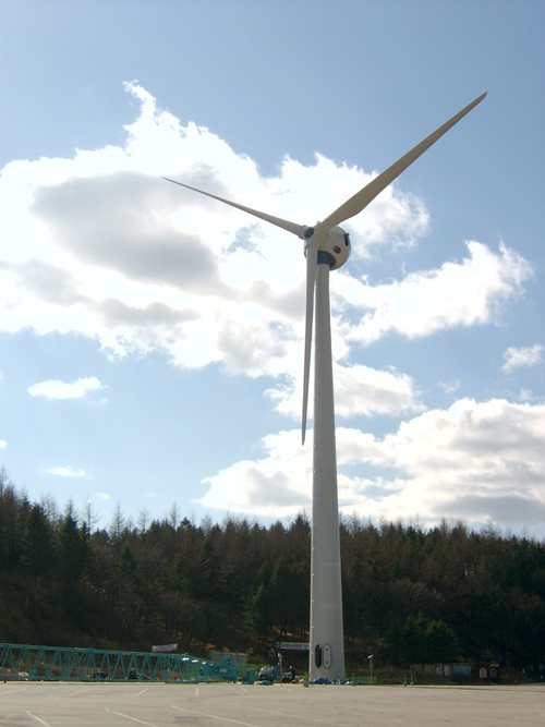
The Unison U50 750 kW wind turbine (Figure 3.23) is among recent designs emerging in east Asia that endorse the direct drive PMG concept. The PMG is overhung downwind of the tower, balancing the rotor weight and giving the nacelle its characteristic shape.
Figure 3.23: Unison U50
Source: Unison
There is growing interest in high temperature superconducting (HTS) generators as a route to low weight direct drive generators. In this case “high temperature” implies having rotor coils cooled to around -200 degree Celsius, near the vaporisation point of liquid nitrogen. Originally the superconducting property whereby currents could flow with negligible resistance losses applied only at much lower temperatures where helium liquefies near absolute zero on the Kelvin scale. Such generators are still some years from commercial production for wind turbines but promise efficiency gains and a weight reduction of the order of 30 to 50 per cent compared to present direct drive PMGs.
HYBRID
Designs with one or two stages of gearing, but not involving high speed two or four pole generators are classified here as ‘hybrid’. Such designs of Clipper Wind, WinWinD and Multibrid are reviewed in 'Alternative drive train configurations'. These designs also maintain the trend towards PMG technology.
FULLY RATED CONVERTERS
The DFIG route was discussed in Speed Variation. It has been predominant and will probably endure for some time in the high volume markets of Asia, for example, but is being challenged by more stringent network requirements, efficiency benefits of PMG technology and advances in power converter technology.
| << Speed variation | Hub height >> |
| Acknowledgements | Sitemap | Partners | Disclaimer | Contact | ||
|
coordinated by  |
supported by  |
The sole responsibility for the content of this webpage lies with the authors. It does not necessarily reflect the opinion of the European Communities. The European Commission is not responsible for any use that maybe made of the information contained therein. |

